[Reprinted from Ocean Magnetic Observations, 1905-1916, and Reports on Special Researches. By L. A. Bauer, with W. J. Peters, J. A. Fleming, J. P. Ault, and W. F. G. Swann. Carnegie Institution of Washington Publication 175, vol. 3 (1917). Pages 160-163]
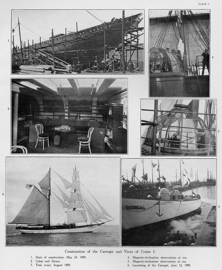
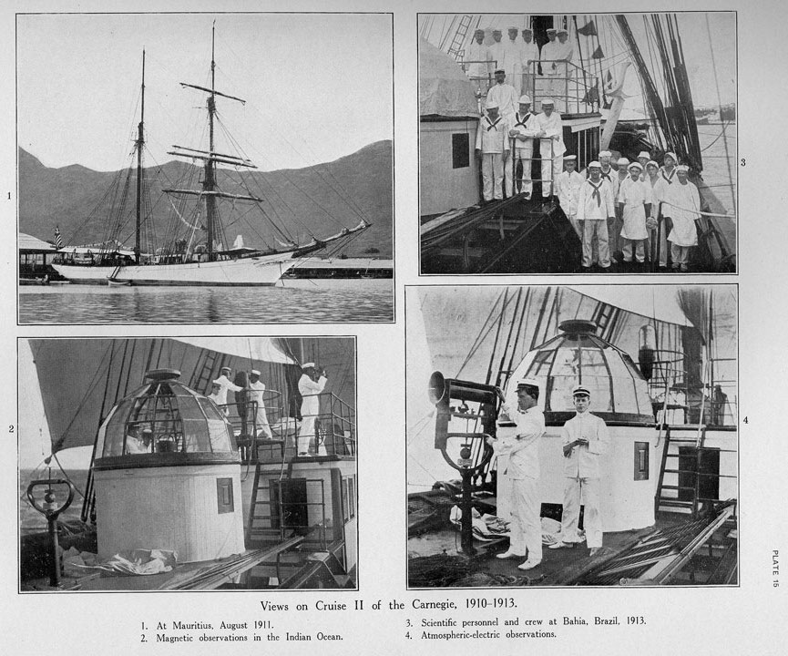
The principal dimensions of the Carnegie are: Length over all, 155 feet 6 inches; length on load water-line, 128 feet 4 inches; extreme breadth, 33 feet 6 inches; depth of hold, 12 feet 9 inches, with a mean draft of 12 feet 7 inches*, and a displacement of 568 tons with all stores and equipment on board. Her lines, as will be seen from the frontispiece and Plate 7, Figure 3, and Plate 15, Figure 1, are fair and easy, running in an unbroken sweep from stem to stern, and showing strength and seagoing qualities throughout. (See also Figs. 8 and 9.)
 |
| Plate 7 |
 |
| Plate 8 |
 |
| Plate 9 |
 |
| Plate 10 |
 |
| Plate 15 |
 |
| Plate 16 |
 |
| Plate 18 |
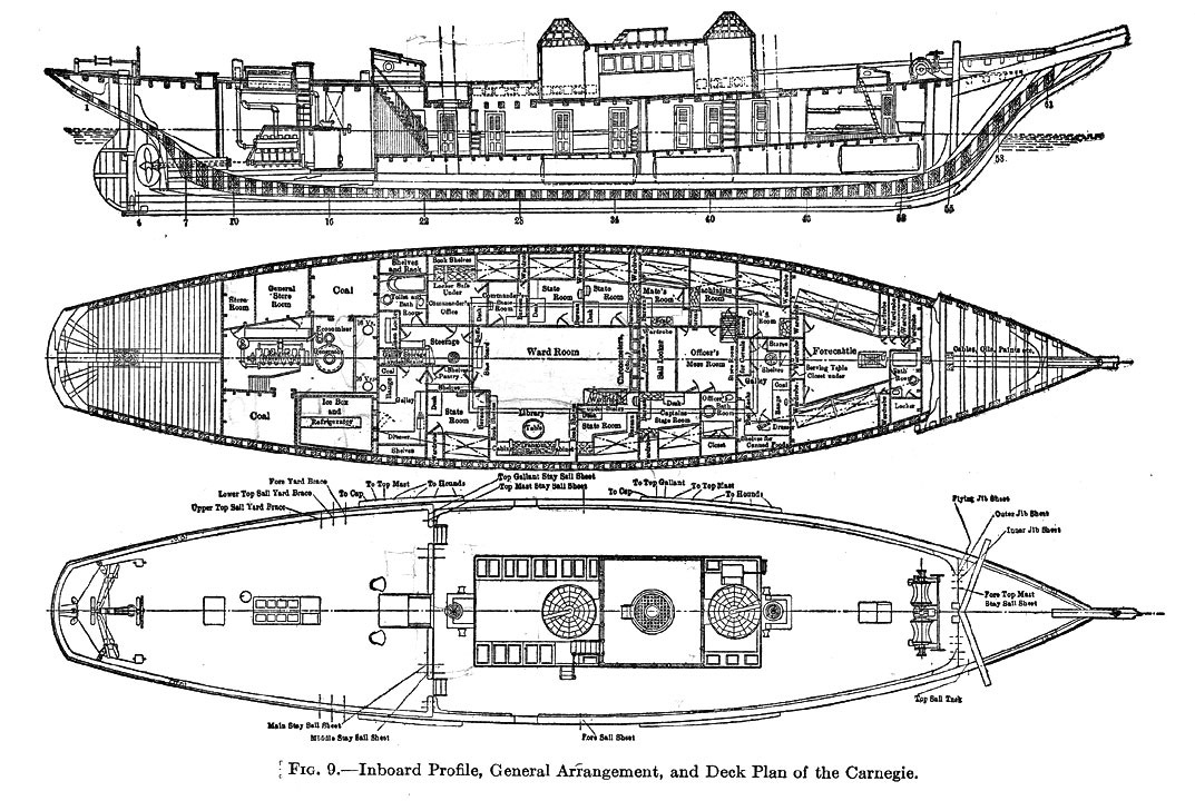
All the materials entering into the construction of the vessel are non-magnetic and are the very best of their kind. The hull is constructed as thoroughly and substantially as any merchant vessel afloat, the scantlings being the same as those required by the American Bureau of Shipping for merchant vessels of equal tonnage. The keel, stem, stern post, frames, and dead-wood are of white oak, grown, cut, and sawed in Greater New York – at Jamaica Plains – within 12 miles of the place where the vessel was built; the deck beams, planking, and ceiling are of yellow pine, and the deck is of Oregon pine in long lengths, comb-grained. The keel (see Fig. 9 and Pl. 8, Fig. 5) is 12 by 18 inches, and to this is fitted a false keel, 12 by 4 inches. There are two center keelsons, each 12 by 14 inches, and two assistant keelsons, 12 by 12 inches. The garboard strakes are 6 by 12 inches, rabbeted into the keel. The planking on the bottom is 3 inches thick; at the bilge 4 inches, and on the sides 3 1/2 inches. The ceiling in the bottom is 3 inches thick, at the bilge 6 inches, and on the sides 4 inches. The main deck beams are 8 by 10 inches, with a crown of 3 1/2 inches at the center of the ship. They are joined to the frames with hackmatack knees of 8-inch siding.
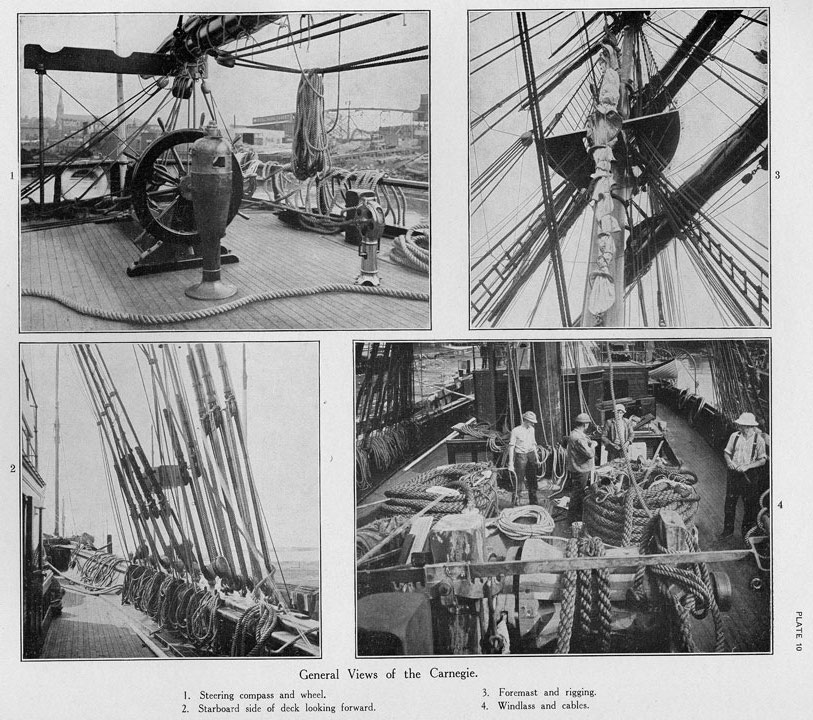
The fastenings consist of locust treenails, copper and Tobin-bronze bolts, and composition spikes, all through bolts being riveted over rings, both inside and outside. All metal deck fittings and the metal work on the spars and rigging are of bronze, copper, and gunmetal (see Pl. 10).
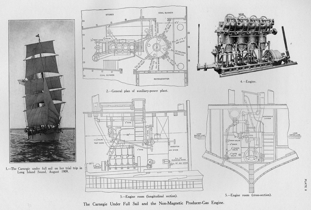
The vessel has full sail power with a brigantine rig, carrying just under 12,900 square feet of plain sail. Her spar plan measures 122 feet from foremast truck to the water surface, and 201 feet from the forward end of the bowsprit to the aft end of the main boom. The distance from the forward end of the bowsprit to the forward end of the load water-line is 48 feet; from the forward end of the load water line to the foremast 35 feet; from the foremast to the mainmast 48 feet. The rigging is of Russian hemp. Figure 8 shows the sail plan. (See also Plate 7, Figure 3, Plate 8, Figure 1, Plate 15, Figure 1, and Plate 17, Figures 2 and 5.)
It was decided to install auxiliary propulsion for use in entering or leaving ports and to prevent interruptions in the observations by maintaining desired headway during calms. The necessity of providing auxiliary propulsion which would be nearly non-magnetic in character made the selection of the type of the plant a rather difficult matter. Steam was precluded on account of the necessarily high magnetic nature of a steam plant. The only type of prime mover at the time (1909) which could be economically built and maintained in reliable operation with a minimum of non-magnetic metals in its construction appeared to be an internal-combustion engine. (See Pl. 8, Figs. 2-5.)
 |
| Figure 8: Sail plan |
Consideration of the available fuel for such a motor resulted in the elimination of gasoline or oil, not only on account of cost, but also because they would be usually unavailable in the zones to be covered by the Carnegie, as well as dangerous in the quantities which would have to be stored for the lengthy voyages contemplated. A careful investigation showed that a gas-producer for marine purposes could be built which would generate from anthracite coal a suitable gas for use in internal-combustion engines and that such a plant could be constructed almost entirely of non-magnetic materials. The suction type of gas-producer was adopted, principally because of its simplicity in construction and operation and on account of eliminating as much as possible other auxiliary apparatus.
A 4-cylinder Craig internal-combustion engine of 150 horsepower (Pl. 8, Fig. 4), sufficient to give the vessel a speed of 6 knots in calm weather, was installed. The gas-producer was furnished by the Marine Producer-Gas Company of New York and consists of a cylinder 6 feet high with a diameter of 5 feet 6 inches, built of copper, with asbestos and firebrick lining and manganese-steel grates. Anthracite coal is used as fuel, the gas being; generated in the producer, taken through a "scrubber," and used explosively in the internal-combustion engine. The vessel carries 30 tons of coal in her bunkers. Non-magnetic manganese steel was used for the doors, grate, and small parts of the producer. The only magnetic material used in the construction of the bronze engine is in the steel valves, piston-rings, cam-springs, and cam-rollers. The total magnetic material was less than 600 pounds. Plate 8, Figures 2-5, shows the various parts and general arrangement of the power plant.
 |
| Figure 9: Layout |
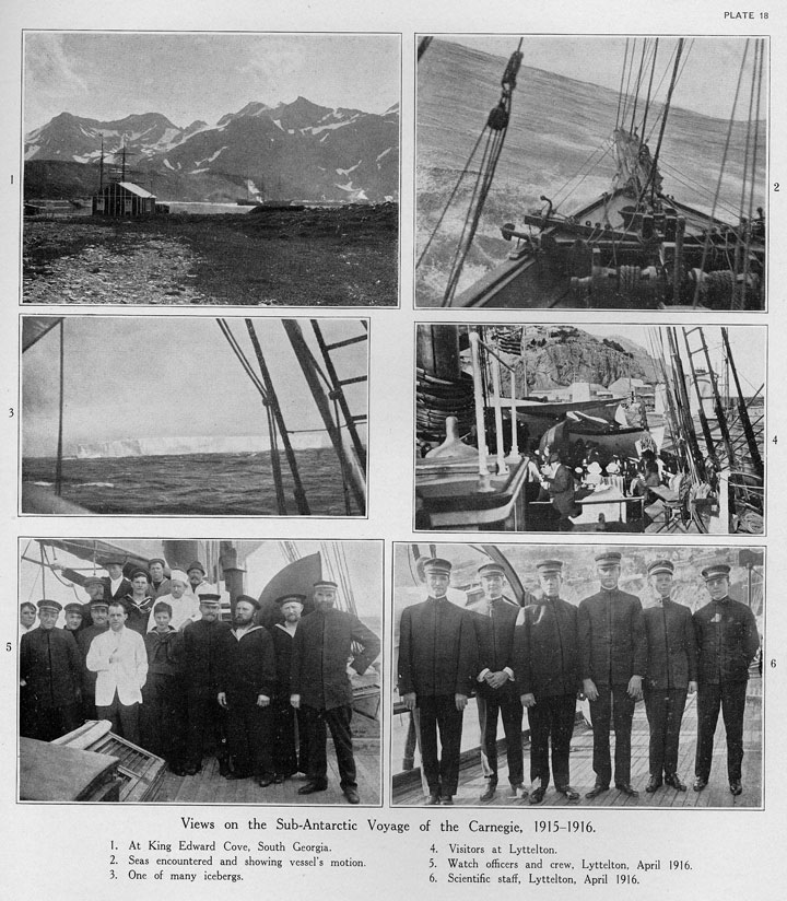
The ground tackle comprises 4 manganese-bronze anchors of special design – 2 being of 1,900 pounds each, 1 of 1,335 pounds, and a kedge anchor of 340 pounds. Three 11-inch cables, each 120 fathoms in length, are required for these anchors. The hawse-pipes, boat davits, chain plates, and all metal deck fittings are of bronze. A fisherman's windlass (see Pl. 10, Fig. 4, and Pl. 18, Fig. 2), constructed of wood and brass, is used to weigh anchor. (A view of propeller blades is shown on Pl. 17, Fig. 3.)
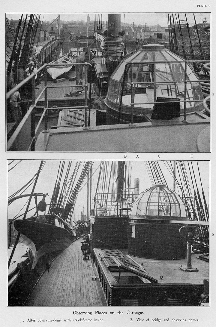
The boat equipment consists of two non-magnetic 20-foot whaleboats and one 16-foot non-magnetic gig (see Pl. 9).
There was provided a refrigerating plant constructed of bronze and copper and operated by a 6-horsepower engine, especially designed and built of brass and bronze.
All living quarters are below; the ventilation and lighting being obtained by means of a cabin trunk on deck about 42 feet 8 inches in length, 16 feet 6 inches in width and 3 feet in height, and safety is secured by means of 6 transverse watertight bulkheads dividing the vessel into 7 compartments. The sailing officers' and crew's quarters are forward, 42 feet in length and occupying the full width of the vessel; next are the quarters for the scientific staff, 38 feet in length and extending the full width of the vessel; and abaft of these is the machinery space, 23 feet in length. The living quarters have been planned to give good accommodations for all, and are fitted with the necessary conveniences for long cruises. Figure 9 gives the inboard profile of the Carnegie and shows the general arrangement of the vessel and her deck plan. (See also Pls. 9, 10, and 15.)
There are 2 galleys, one aft for the scientific personnel and the other forward for the watch officers and crew, especially designed cooking ranges of bronze and copper being provided. The galley utensils are made of aluminum or copper and the cutlery is of Mexican silver.
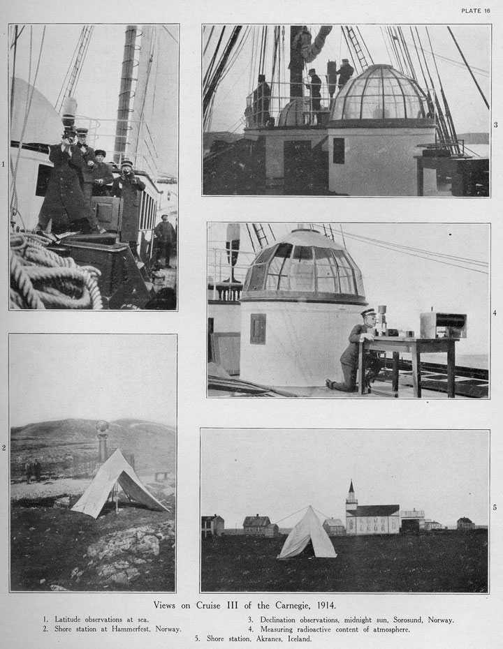
Of special interest is the observation room, or deck house, located on the main deck amidships, forward and aft of which are circular observatories with revolving domes not unlike those of astronomical observatories (see Pls. 7, 9, 15, and 16).** It is thus possible to make magnetic observations both in the open and under shelter. The observation room is 14 feet 6 inches long and 16 feet wide. The observatories are circular, 7 feet 6 inches in diameter, each fitted with a revolving dome, constructed of bronze framework and plate glass so arranged as to permit sighting, whenever desirable, on celestial or terrestrial objects in magnetic-declination work. The joiner-work is of white pine, painted, with hardwood trimmings finished bright.
The positions of the stands for the various instruments have been so chosen that any effect resulting from the small amount of iron in the engine, which could not be replaced by non-magnetic material, is negligible. (See pp. 202-203.) To eliminate further any possible magnetic effect, empty spaces are arranged around and below the instrument stands, making it impossible for any one, except the observers, to come closer than about 8 feet to the magnetic instruments while observations are in progress.
The total cost of the Carnegie, fully equipped, approximated $115,000.
* This was increased in 1914 about 15 inches.
** In 1915 there was added abaft the after observing-dome an observation-house for the atmospheric-electric work (see p. 376 and Pl. 22, Fig. 1).